Click here to go to the on-line version The Embedded Muse 496

The Embedded Muse Logo The Embedded Muse
Issue Number 496, August 19, 2024
Copyright 2024 The Ganssle Group

Editor: Jack Ganssle, jack@ganssle.com

   Jack Ganssle, Editor of The Embedded Muse

You may redistribute this newsletter for non-commercial purposes. For commercial use contact jack@ganssle.com. To subscribe or unsubscribe go here or drop Jack an email.

Contents
Editor's Notes

SEGGER embOS Ultra Cycle-resolution accurate RTOS

Tip for sending me email: My email filters are super aggressive and I no longer look at the spam mailbox. If you include the phrase "embedded" in the subject line your email will wend its weighty way to me.

Quotes and Thoughts

The sooner you start to code, the longer the program will take. - Roy Carls

Tools and Tips

Please submit clever ideas or thoughts about tools, techniques and resources you love or hate. Here are the tool reviews submitted in the past.

Here's some useful advice, especially for novices, about building firmware.

A reader posed an interesting question: How many of you are using any sort of model-based design? Please let me know, and tell me what sort of tools you use, and how well these are working out for you. I'll share the results in a future Muse.

Libero

Paul Amaranth has some thoughts on Libero:

I was working on a project that quite naturally fit into the case where an FSA would be of use to structure the code.  While useful, manually building FSAs rapidly gets untenable and difficult to maintain, so I spent some time researching the available tools.  Many of these have little to recommend them beyond the manual construction method.

However, I did run across mention of a tool called libero.  This tool was developed by Pieter Hintjens in the 1990s.  Sadly Pieter is no longer with us, but he was an absolute genius.  In short, the tool allows you to write a description of an FSA in a structured format called a dialog.  This is completely language agnostic.  The tool translates the dialog into a source file for the language of your choice using a template file.  Templates are provided for C, C++, java, php, awk, vb, sql, shell and even Cobol, among others.  The generated source is then compiled as usual.  The tool itself is written in ANSI C and can be compiled with minimal alterations using gcc.

For reasons too unimportant to go into, this particular project was to use the Arduino programming environment.  It took very little effort to modify the state machine code and template files to get a working tool for that environment.  I only mention this to underscore the effectiveness and flexibility of the tool.

The only point lacking in the package is the presence of sufficiently complex examples to highlight the utility and brilliance of the software.  Working from the included examples it may take a day or two of effort to start to understand how to effectively apply the tool. but the effort is well worth it.

Let me give a short description.  A dialog consists of states, events, actions and next-state clauses. This is the basic structure of a dialog
clause:

Statename:
               (--) Event  -> [NextState]
               + Action
               + Action
               ...

A Statename starts the clause with one or more events that have 0 or more actions. Events are identified with a line starting with (--).
After the event, are 0 or more actions which are executed before transitioning to the state after the arrow. If the next state is left off, the system remains in the current state after completing the actions.

Here is a sample from a dialog for a signature analyzer test instrument. The primary event loop remains in Expecting-Event until something of interest happens, either a button press from the front panel, or an internal signal generated from the hardware:

!================================================================
! This is the primary state for running the signature  analyzer ! 
!Look for events and handle them.   Everything is handled in ! this state except for configuration !
! Almost all events end up calling Get-Next-Event as the  last ! action.
!================================================================
Expecting-Event:
 (--)  LongButton           -> Config-Clk-Pol
    +  Display-Config-Clk-Pol
    +  Get-Next-Event
 (--)  ShortButton          ->
    +  Start-acq-if-single-shot
    +  Get-Next-Event
 (--)  Sig-Start            ->
    +  Set-triggered-ind
    +  Get-Next-Event
 (--)  Sig-Stop             ->
    +  Update-Sig-Display
    +  Get-Next-Event
!================================================================
! In configuration, turning the dial moves you through  the config
! menus.  Pressing  the button toggles the value and a long push
! saves the values, leaves the config function and  returns to 
! the main screen.   This is modified a bit for the logic thresholds
!
! First config state toggles the Clock polarity
!================================================================
Config-Clk-Pol:
  (--)  Dial-Plus            ->  Config-Start-Pol
     +  Display-Config-Start-Pol
     +  Get-Next-Event
  (--)  Dial-Minus           -> Config-Mode
     +  Display-Config-Mode
     +  Get-Next-Event
  (--)  ShortButton          ->
     +  Toggle-Clock-Polarity
     +  Get-Next-Event
  (--)  LongButton           ->  Expecting-Event
     +  SaveConfigValues
     +  Display-Main-Screen
     +  Get-Next-Event
  
The actions get compiled into stubs that can be expanded to do what is required. As with any programming activity, choosing the granularity of the actions can make the difference between something readable and maintainable and an absolute mess. If the actions are effectively chosen, the behavior of the system can be changed simply by moving the actions and changing the state machine. It is easy to expand or modify the system.

A very short introduction to Libero can be found on the web at
https://imatix-legacy.github.io/libero/lrintr.htm
This only hints at the power of the tools.

There is also a collection of newsletters in the liberetto directory that make for very interesting reading.

Pieter's company, IMatrix, also had a number of other interesting tools that are available in the repository.  I hope you will share some of this with your readers so that Pieter's legacy gets the exposure it deserves.

More on Rejecting Outliers

Several readers responded to last issue's thoughts on outliers:

Niklas Holsti wrote:

For rejecting outlier samples, I have had success with a method called Random Sample Consensus, described in https://en.wikipedia.org/wiki/Random_sample_consensus, which includes example code. This method is especially good at rejecting extreme outliers because it tries to do its initial fits using the minimum possible number of samples, so a few extreme outliers are likely to be completely excluded from those fits and then cannot skew them at all.

There's this from Caron Williams:

I had an application measuring light absorbance. For some reason I never satisfactorily explained, the hardware would return completely off-the-wall values, at random,  about 5% of the time. I think it was an internal timing coincidence within the System-On-A-Chip we were using. So I just accumulated 15 values (magic number), did a quicksort, and chose the middle value as the result. This worked very well eliminating the outliers, even though it does seem counterintuitive to "throw away" the other 14 values. However, statistically, it's a valid approach. I then performed further statistics on the stream of results, and ended up with excellent accuracy from a simple and inexpensive optical system. 

Remember C Snippets? Bruce Wedding does:

Your writing about filtering reminded me of Bob Stout's (C Snippets fame and FidoNet moderator) Olympic Filtering. Bob left this earth many years ago but was ahead of his time in many ways. I'm happy to say I knew him personally, as we both lived in Houston. Here's his article and code on Olympic Filtering. Keep in mind, this code was written in the 90s.
CUJ/13.03/stout/stout.md at master · eugnsp/CUJ · GitHub

TTL at 60

2024 marks the 60th anniversary of the birth of TTL logic. Wikipedia says that, though TTL was invented in 1961, TI released the 54 family in 1964, and that the 74 series in plastic came out two years later. Since TTL is practically synonymous with the 54 and 74 series, why not offer 60th birthday congratulations?

Remember that the IC was invented just a few years before TTL came out. Other kinds of logic were commonly used, like DTL (diode-transistor logic) and RTL (resistor-transistor logic). In fact, the Apollo guidance computer was made entirely from RTL components, using several thousand identical ICs, each containing a pair of three input NOR gates.

The Apollo guidance computer IC.

The schematic is clear: RTL logic was barely digital. It wasn't uncommon for RTL users to bias the transistors nearly linearly and use them as amplifiers. But RTL persisted into the 70s, and in the late 60s we were using gobs and gobs of Fairchild parts for Apollo ground support equipment.

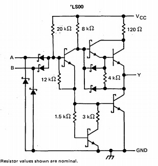
The perfect gate can only assume two states, and RTL's linearity was exactly the opposite of what the digital world strived for. TTL was designed to approach that ideal. Like an op amp we also want zero output impedance, and many TTL gates used a "totem pole" configuration of transistors to offer plenty of drive and sink capability.

A 74LS00 dual-input NAND gate. Note the "totem pole" output transistors.

As mentioned, the anonymous experts at Wikipedia believe the 54 series predated the much more common 74 family by a couple of years. The main difference between the two was the temperature range; 54-series devices generally operated from -55 to 125C, while the 74 parts, housed in inexpensive plastic packages, were rated from 0 to 70C. Though the 54 family was often called the :military" version, a lot of commercial applications demanded their extended temperature range.

TTL devices were either SSI (small scale integration), which meant one package contained a couple of flip flops or a few gates, or MSI (medium scale integration), which were more complex parts like multiplexors. The 74181 was an example: it contained an ALU that could add, subtract and do logic operations on two four-bit inputs. The DIP package had 24 pins, which was enormous in those days.

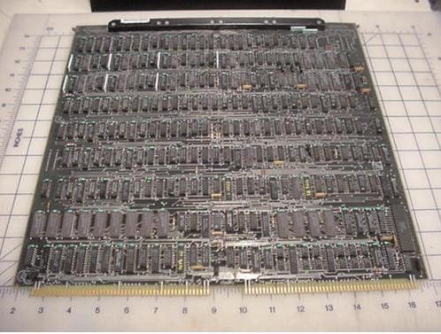
By the late 60s most computers had oceans of TTL components. The following picture is the CPU board from a Nova 1200 16-bit minicomputer. There were no MOS memories at the time; another board held core memory. All of these DIP packages are 74-series TTL devices.

A Nova logic board. The dimensions are in inches. These boards were enormous.

Components were so expensive that the earliest Novas used one 74181 four-bit ALU; it pushed a word through one nibble at a time.

As time went on many versions of the 74/54 devices appeared. 74LS parts were lower power and faster than the original components. 74HCT used less power. Today there are a dizzying number of families, and it can be a chore to pick a component from the cornucopia. I've been using 74AUC08 gates recently, which are blazing-fast.

Most of the early parts are unavailable today. Digi-Key doesn't list any 74-series parts, though they still supply 74LS and some others that are well into their dotage. Only 13 DIP devices appear from the thousands of TTL part numbers they sell.

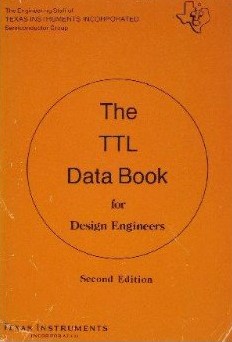
Though lots of vendors sold, and still sell, 74 logic, old timers remember the industry bible: TI’s TTL Data Book. For many years it was beautifully hard-bound, though later editions were paperbacks. Every year it got thicker till they started producing multi-volume sets. Once a year the distributors would have an open-databook day; we’d fill the trunks of our cars with books about all sorts of components. Pre-PDF, pre-Internet, these tomes were how we sourced parts. The paperless office never appeared, but the datasheetless office sure did. PDFs are great as they are mostly up-to-date and take no room. And modern datasheets can be enormous, running to thousands of pages for a single component. But it sure was nice to have many books open on the bench or the drawing board.

Oh, a "drawing board" was a six-foot long tilting table where engineers drew their schematics using "pencils," "drawing machines," and a variety of other tools. But that's another bit of ancient history.

The TTL Data Book, by TI.

Failure of the Week

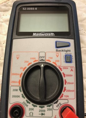
Michael Dunn sent this, a change from the many software failures I run:

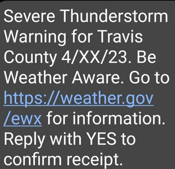
Matt Bennett sent this:

Have you submitted a Failure of the Week? I'm getting a ton of these and yours was added to the queue.

Jobs!

Let me know if you’re hiring embedded engineers. No recruiters please, and I reserve the right to edit ads to fit the format and intent of this newsletter. Please keep it to 100 words. There is no charge for a job ad.

Joke For The Week

These jokes are archived here.

"Always code as if the guy who ends up maintaining your code will be a violent psychopath who knows where you live."
- Martin Golding

About The Embedded Muse

The Embedded Muse is Jack Ganssle's newsletter. Send complaints, comments, and contributions to me at jack@ganssle.com.

The Embedded Muse is supported by The Ganssle Group, whose mission is to help embedded folks get better products to market faster.

Click here to unsubscribe from the Embedded Muse, or drop Jack an email.