| ||||
|
You may redistribute this newsletter for non-commercial purposes. For commercial use contact jack@ganssle.com. To subscribe or unsubscribe go here or drop Jack an email. |
||||
| Contents | ||||
| Editor's Notes | ||||
Tip for sending me email: My email filters are super aggressive and I no longer look at the spam mailbox. If you include the phrase "embedded" in the subject line your email will wend its weighty way to me. |
||||
| Quotes and Thoughts | ||||
|
I have succeeded getting my actual work down to 30 minutes a day. That gives me 18 hours for engineering. Charles Steinmetz. |
||||
| Tools and Tips | ||||
Please submit clever ideas or thoughts about tools, techniques and resources you love or hate. Here are the tool reviews submitted in the past. |
||||
| Margin! | ||||
|
When I was a kid my dad, who was a mechanical engineer, related a story about his work on the F-11F fighter airplane. It seems Grumman was testing the tail assembly using hydraulic actuators to attempt to make it fail - break in two. The tail was tougher than the test jig and nothing broke. The customer - the US Navy - was pretty unhappy about this as it meant that unit was stronger than necessary. Stronger meant heavier, which translated into decreased performance. Eventually an antenna snapped off and they reluctantly accepted that. The point of the story was that the engineers had designed a ton of margin into it. Years passed and now I was a young engineer. A smart technician did a design review on one of my schematics. He was an incredible pain in the rear end. Annoying. Critical. Nitpicking. "Why is that pullup 10k?" "Have you computed what happens if all of those resistors are at the low end of their tolerance band?" "Prove this combinatorial won't create a race condition!" "What happens if the power supply is a bit low?" Hours of challenging and unpleasant criticism flowed from his scathing tongue. Hey, this was my design, my proud baby! How dare he! But he was right. My dad's story, and the technician's review, taught me two things: One: Be critical. Do worst case analysis. Never assume... anything. Things will be worse than you can expect. Two: Take every opportunity to add margin to your design. Yeah, it might add weight to the plane, but if the customer doesn't care, that margin might keep it flying in adverse conditions. Maybe the design goal is for a stable amplifier over -10 to +40 degrees C... but what if you can make it handle just a few degrees more? Vcc will always be +/- 5%,but, hey, we can make this baby work even if it falls a bit lower than that. Margin is our friend. Margin will sometimes have unacceptable costs. I remember them chemically milling the lunar module panels to extract every gram of weight from that spacecraft. I'm sure the engineers were dying to add a couple of thousands of thickness, but the realities prevented that. But if we can design margin in, that can make a product much more robust than anticipated. The slings and arrows of outrageous fortune always seem ready to pounce on a design. "Madman" Muntz would prowl the engineering labs with a pair of wire cutters, snipping components out of the TVs and radios his engineers were working on. If the device continued to work he'd give the engineer an metaphorical slap as the part was "unneeded"; removing it would shave a few cents off the production costs. I always shudder when thinking of this. Did that part insure correct operation when the room temperature dropped a few degrees? Or keep the horizontal sweep operating when the 6AL6 aged and it's mu degraded? Margin also applies to software. Is the CPU 99.9% loaded in cycles? If so something bad is likely to happen. But there's a more fundamental sort of design margin in software. When we read a sensor, for instance, be sure it makes sense. Does that reading square with the physics of the parameter being sensed? Readers have shared hundreds of examples where crazy stuff was accepted by the code, like an outdoor thermometer reading 500 degrees. Does the sensor reading align with other recent measurements? If a thermistor has been indicating 25 degrees for the last half hour, a sudden jump to 90 may indicate a sensor failure. The flight data recorders in the two 737MAX crashes showed the angle of attack sensor going from zero degrees to 70 in under a second. First: that impossibly-rapid transition surely indicates a problem with the sensor. Second, other data channels showed the airspeed unchanged. A rapid change in attitude would surely cause a quick speed bleed-off. Other channels also showed no indication the aircraft had rotated. All the data was there to show the sensor had malfunctioned, but the software ignored that. There was no design margin. Only catastrophic failure. I think the 737MAX failure offers us a profoundly disturbing lesson for all of us, and I plan to write more about this in the coming months. |
||||
| Fourier and Us | ||||
|
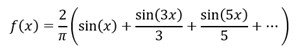
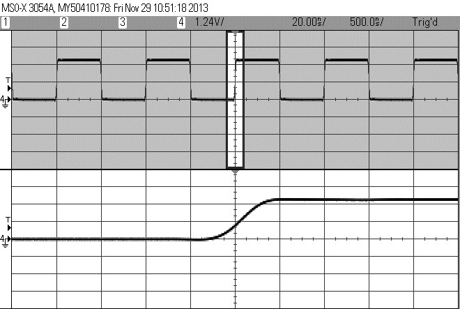
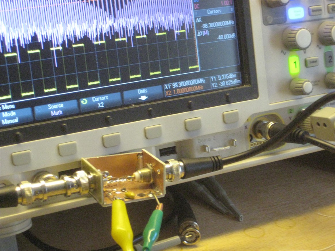
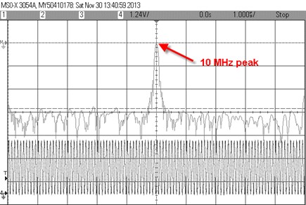
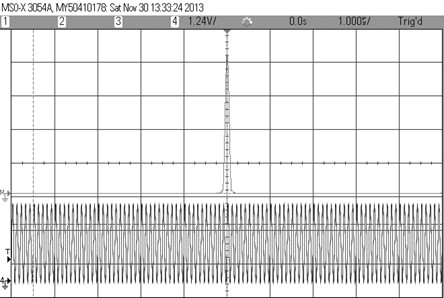
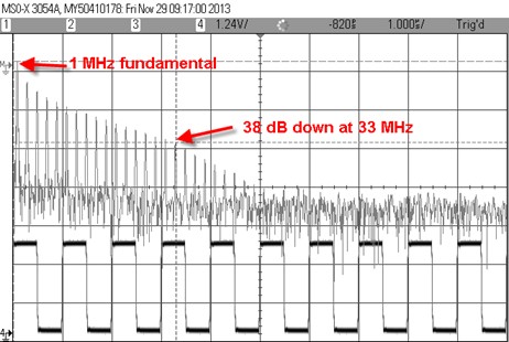
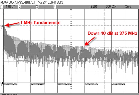
In my seminars I would often talk about the importance of understanding at least a little electromagnetics theory, even for purely firmware people. But the subject is hard to understand and sometimes harder to believe, which is why the best book on the subject, “High Speed Digital Design,” is subtitled “A Handbook of Black Magic.” Why is it important? You’ll surely be probing your design with various tools like scopes and logic analyzers, and every such probe has some impedance. As speeds get higher, that impedance is ever more likely to corrupt the operation of the device. But “speed” is poorly understood today. We equate clock rate with speed, which is only part of the story. Almost two hundred years ago polymath Jean-Baptiste Joseph Fourier showed that any periodic function can be expressed as the sum of sine waves of different amplitudes and frequencies. A square wave, like a microprocessor clock, is periodic and its Fourier series is: In other words, a square wave is composed of the sum of the sine of the wave’s frequency and each of its odd harmonics. (A harmonic is an integer multiple of the base frequency.) As you can see, no matter what the square wave’s frequency is, it has harmonics that go to infinity, though at progressively lower amplitudes. A useful rule of thumb is that for most digital design we can ignore harmonics that exceed: f=0.5/Tr ... where Tr is the square wave’s rise time in nanoseconds. Every real-world signal takes time to transition from a zero to a one. Above f the Fourier components are down about 40 dB. Since a picture is worth a million bits, look at the following scope trace: A square wave with 20 ns rise time. The top trace is a 1 MHz square wave, just like a CPU clock. The bottom is an expanded view of the highlighted portion of the same trace. Note that what looks like a nice, quick zero to one transition actually takes quite a bit of time. In this case the rise time is 20 ns. Running 20 ns through the previous formula and it’s clear that anything above 25 MHz will be so far down we don’t have to worry about them. But it does mean that 1 MHz signal has important frequency components that far exceed the fundamental. That square wave comes from my scope’s waveform generator. To show the Fourier effect more dramatically I built a circuit to improve the signal’s rise time by feeding the signal through a fast gate. It is possible to see the individual frequency components predicted by the Fourier series. Most modern scopes can compute the Fourier transform of a signal, as in the following screen capture. The bottom trace is a simple 10 MHz sine wave. Above it is the Fourier transform. Unlike a normal scope display where the horizontal axis is time and the vertical volts, the upper one is displayed in units of dB and frequency. In this case the screen’s scale is set to 0 MHz at the left and 20 MHz all the way to the right. Note there’s a very strong peak exactly at 10 MHz, because 10 MHz is the only frequency component in a 10 MHz sine wave. Sure, there are some other things running around on that trace due to an imperfect waveform generator and some artifacts of the Fourier transform process. But the ugly stuff is 57 dB lower than the peak. That’s 1/500,000 less than the 10 MHz peak. Switching from dB to voltage makes this more obvious: Here’s the Fourier transform of the 20 ns rise time square wave: The bottom trace is the 1 MHz square wave from the scope’s waveform generator, before going to the fixer-upper circuit. Above it is the Fourier transform. In this case the screen’s scale is set to 0 MHz at the left and 100 MHz at the right. Each peak is one of the square wave’s odd harmonics from the Fourier series. Unsurprisingly, the highest peak is at the wave’s fundamental frequency of 1 MHz. At 33 MHz the signal is down 38 dB, and quickly rolls off from there. That’s close enough to the rule of thumb for practical work. With the fixer-upper circuit the rise time is now 1 ns: Spectrum of a square wave with 1 ns rise time. This looks different from the previous picture because now the Fourier transform window goes from 0 MHz to 500 MHz. There are a lot more harmonics displayed. But notice that the 40 dB point is now at 375 MHz (the formula predicts 500 MHz, again, close enough for a rule of thumb). It’s important to remember that this is the spectrum of the same 1 MHz signal; all that has changed is the rise time. If your little 8 bit system is clocking at just a few MHz, or even hundreds of KHz, with sharp edges it may have all of the same high speed issues we usually attribute to much faster circuits. Sounds hard to believe. Some time ago a company asked for help with their 30 year old, 4 MHz, Z80 design. A new batch of boards didn't work, though the design was unchanged. It seems the semiconductor vendor had increased the speed of some of the logic. Those gates that used to switch in 15 ns now did it in 5. The company had to redesign this board as a high-speed digital system simply because of the faster rise time. The takeaway is that we can't think of digital signals as we do simple sine waves. They are composed of a lot of harmonics, and, depending on rise time, those harmonics can have a huge effect on the circuit’s operation. A 1 MHz clock does not necessarily imply a slow circuit. |
||||
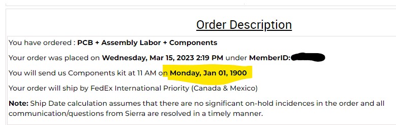
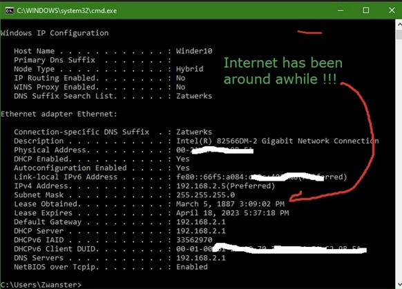
| Failure of the Week | ||||
From Martin Fuhrer: Gary Olzeke found this after a reset: Have you submitted a Failure of the Week? I'm getting a ton of these and yours was added to the queue. |
||||
| Jobs! | ||||
|
Let me know if you’re hiring embedded engineers. No recruiters please, and I reserve the right to edit ads to fit the format and intent of this newsletter. Please keep it to 100 words. There is no charge for a job ad. |
||||
| Joke For The Week | ||||
These jokes are archived here. Documentation is like sex: When it's good, it's fantastic, when it's bad... |
||||
| About The Embedded Muse | ||||
|
The Embedded Muse is Jack Ganssle's newsletter. Send complaints, comments, and contributions to me at jack@ganssle.com. The Embedded Muse is supported by The Ganssle Group, whose mission is to help embedded folks get better products to market faster. |