|
|
||||||||||
You may redistribute this newsletter for noncommercial purposes. For commercial use contact jack@ganssle.com. |
||||||||||
| Contents | ||||||||||
| Editor's Notes | ||||||||||
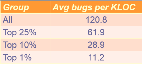
Are you a member of the 1%? I don't mean the economically elite; rather, the software engineering elite. Those who inject just about 11 bugs, in requirements gathering through coding, per thousand lines of code. The 99% do much worse, averaging about 120 bugs per KLOC. Wouldn't you want to be in the top tier of developers? That is part of what my one-day Better Firmware Faster seminar is all about: giving your team the tools they need to operate at a measurably world-class level, producing code with far fewer bugs in less time. It's fast-paced, fun, and uniquely covers the issues faced by embedded developers. Information here shows how your team can benefit by having this seminar presented at your facility. Follow @jack_ganssle
I'm now on Twitter. |
||||||||||
| Quotes and Thoughts | ||||||||||
"The competent programmer is fully aware of the strictly limited size of his own skull." - Edsger W. Dijkstra |
||||||||||
| Tools and Tips | ||||||||||
Please submit clever ideas or thoughts about tools, techniques and resources you love or hate. Here are the tool reviews submitted in the past. Dave Harper found a nice x86 compiler:
Phil Ouellette had some comments about FreeRTOS and uEZ-GUI:
He later added:
|
||||||||||
| Freebies and Discounts | ||||||||||
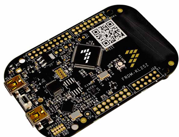
Reader feedback about these giveaways has been very positive. So this month I'm giving away a FRDM-KL25Z development board, which was kindly provided by Freescale. This board has a Cortex M0+ MCU. One neat feature is that it works with the mbed tool chain, which is a web-hosted C compiler. There's nothing to install. For small projects and experiments it's a really fast way to get started. The contest will close at the end of February, 2016. It's just a matter of filling out your email address. As always, that will be used only for the giveaway, and nothing else. Enter via this link. |
||||||||||
| Long-Term Project Support | ||||||||||
In the last Muse there was some discussion about maintaining tools for years to support a code base. Jerry Trantow has an approach that never occurred to me:
In a second email Jerry wrote:
Sergio Caprile agreed:
Bob Snyder has a twist on this:
I had no idea SpinRite works on SSDs. Cogoman01 wrote:
The Wikipedia article is a bit fuzzy on SpinRite's efficacy on solid state drives. Gibson claims it is effective on SSDs, but I'm a bit skeptical. |
||||||||||
| Review of Digilent's Waveforms 2015 and Analog Discovery 2 Oscilloscope | ||||||||||
Richard Wall reviewed Digilent's Waveforms 2015 software and their Analog Discovery 2 oscilloscope, and was kind enough to let me publish it. I reviewed the original Analog Discovery here. I have been designing microprocessor based control systems since 1976 (that's no mistake -- yes for 40 years!) I have worked in industry for 18 years and academia for 25 years. The instruments I have relied on for the vast majority of my hardware diagnostic efforts have been the multimeter and the oscilloscope. Verifying processor input and outputs is fundamental to quality digital systems development. I used a Fluke 100MHz dual channel digital oscilloscope for many years. However, since I acquired a Digilent Analog Discovery and the Windows based Digilent Waveforms software, I have not used the Fluke Oscilloscope. My current processor of choice is the Microchip PIC32® and either the MPLAB X and/or the Arduino IDE. My office environment I most often use is a Windows 8 PC with two monitors. I use the Analog Discovery / Waveforms extensively. I have recently investigated the updated versions called Waveforms 2015 / Analog Discovery 2. The following is a list a few of the advantages of using Analog Discovery system with either the Waveforms or Waveforms 2015.
Waveforms 2015 improvements:
Analog Discovery Improvement Suggestions:
Waveforms 2015 Documentation Improvement Suggestions:
|
||||||||||
| A Simple 'Stateless' Decoder for Quadrature Encoders | ||||||||||
Recently readers have sent in their code and ideas for handling quadrature inputs. Bill Mather submitted a really nice analysis, with code: There are 2 issues here -- ensuring a clean Gray Code (i.e. no invalid states), and doing a correct, fast or low-overhead decode of the valid Gray Code. My research shows no code which correctly handles Gray Code phase errors in all cases, so I looked for a best-case scenario. For debouncing, I follow Tim Wescott's outlook -- make everything as reliable as possible, so my algorithm presumes clean input, provided by hardware debouncing, which for our hardware is a simple RC signal shaper with hysteresis, and a limited pulse repetition rate. My extension to the discussion is to derive the previous state by using edge interrupts (to give the phase changing), and a read of the current phase inputs (to give both current and previous states). The LPC1347 can support separate interrupts for each phase -- the example code is for this CPU. For Gray Code, the rotation direction can be determined by the phase edge and the resulting phase state. After developing my routine, I have found a reference to this technique -- the KL25Z manual MK20DX256VLH7-K20P64M72SF1RM.pdf describes the hardware algorithm in section 36.4.25 Quadrature Decoder mode, page 890. It also appears to ignore phase errors in the decoder. Given the standard Quadrature Encoder / Gray Code signal, and ignoring phase errors:
traversing FWD, the signals are <AB> (00, 10, 11, 01, 00), This gives the same maps as all other algorithms show. However, re-arranging the maps, to be in terms of a single channel instead of in terms of time, two interesting tables result: change ChB (low bit) change ChA (high bit)
0[0] - 0[1] R [0]0 - [1]0 F
0[1] - 0[0] F [0]1 - [1]1 R
1[0] - 1[1] F [1]0 - [0]0 R
1[1] - 1[0] R [1]1 - [0]1 F
dir = (A==B) ? Fwd : Rev; dir = (A==B) ? Rev : Fwd;
This change map demonstrates that on any edge, the direction of rotation is determined by the channel changing its state, and the comparison of the two states after the edge, as per the 'C' ternary code for ChB: dir = (A==B) ? Fwd : Rev; If the pulse repetition rate is limited, and the inputs are decoded in interrupt routines, the overhead for decoding can be determined. With a standard panel input rotary switch encoder such as the Bourns PEL12T with 24 detents per revolution, using a (10K/0.1uF) 1mS RC shaper on each of the encoder signals allowing the ISRs servicing the QEI signals to require a maximum of 1% of CPU capacity, a rotation rate of 10 revs/sec can be supported. This algorithm can be implemented in a simple way in LPC1347 interrupt routines. The physical setup for this example is: Connection: This code requires :
typedef uint32_t QEI_TYPE;
#define ioBIT(port,bit)	( 1ULL << (((port) ? (32) : (0)) + (bit)))
// read current pin state
#define GPIO_GET(mask)	(*((uint64_t *)&(LPC_GPIO->PIN)) & (mask))
#define	iQeiChA		(ioBIT(0, 2))					                    // edge
#define pQeiChA		PIO0_2
#define iQeiChB		(ioBIT(0, 8))					                    // edge
#define pQeiChB		PIO0_8
#define MASK_QEI		(iQeiChA | iQeiChB)

// Rotary-Encoder Interrupt Handler triggered by Phase 0 and 1 Rising AND
// Falling edges
// 1    ___     ___     ___     ___     ___
// 0 __|   |___|   |___|   |___|   |___|   |____    ChA
// 1      ___     ___     ___     ___     ___
// 0 ____|   |___|   |___|   |___|   |___|   |__    ChB
// FWD A B C D A B C D a b c d a b c d back
// change map - when result is (ChA==ChB), then moves in direction X, else
// direction Y
//  change low bit 0[1]                 change high bit [1]0
//          00 - 01 R                       00 - 10 F
//          01 - 00 F                       01 - 11 R
//          10 - 11 F                       10 - 00 R
//          11 - 10 R                       11 - 01 F
//      dir = (A==B) ? Fwd : Rev;       dir = (A==B) ? Rev : Fwd;
//
// Uses switch connected to IO-pin shaped with a 1mSec RC circuit.
//  IO-pin must have HYSteresis enabled, to prevent oscillation on pin during
// switching.

 // dir = (A==B) ? Fwd : Rev
#define QEI_CW(v, p, m)     ((v) += (((p) == 0) || ((p) == (m))) ? 1 : -1)
// dir = (A==B) ? Rev : Fwd
#define QEI_CCW(v, p, m)    ((v) -= (((p) == 0) || ((p) == (m))) ? 1 : -1)


volatile int32_t qeiPosition = 0;

//-----------------------------------------------------------
// - Quadrature Encoder Interface Channel A
//-----------------------------------------------------------
void PIN_INT1_IRQHandler(void)
{
    // grab the current state ASAP
    QEI_TYPE newQEI = GPIO_GET(MASK_QEI);

    // Enable the next interrupt capture.
    // Clear RISING/FALLING EDGE interrupt flag
    LPC_GPIO_PIN_INT->IST = (1UL << PIN_INT1_IRQn);

    // Process the edge
    QEI_CCW(qeiPosition, newQEI, MASK_QEI);
}

//-----------------------------------------------------------
// - Quadrature Encoder Interface Channel B
//-----------------------------------------------------------
void PIN_INT2_IRQHandler(void)
{
    // grab the current state ASAP
    QEI_TYPE newQEI = GPIO_GET(MASK_QEI);

    // Enable the next interrupt capture.
    // Clear RISING/FALLING EDGE interrupt flag
    LPC_GPIO_PIN_INT->IST = (1UL << PIN_INT2_IRQn);
    // Process the edge
    QEI_CW(qeiPosition, newQEI, MASK_QEI);
}

//-----------------------------------------------------------
// GPIO pin interrupts configuration
//-----------------------------------------------------------
// GPIO pin interrupt 1 set for: QeiChA triggered with BOTH EDGE
// GPIO pin interrupt 2 set for: QeiChB triggered with BOTH EDGE
// Need to set HYS to prevent chatter on RC signal rise/fall time.
//-----------------------------------------------------------
void SetupQeiDecoder (void)
//-----------------------------------------------------------
{
    // enable clock for GPIO pin interrupt (default is disabled)
    LPC_SYSCON->SYSAHBCLKCTRL |= (1UL << 19);

    // Set to: PIO, No PU/PD, HYSteresis
    LPC_IOCON->pQeiChA    = (1L << 5);
    // Set to: PIO, No PU/PD, HYSteresis
    LPC_IOCON->pQeiChB    = (1L << 5);
    // use edges for INTs
    LPC_GPIO_PIN_INT->ISEL = (ISEL_EDGE << QEI_INT_CHA
                            | ISEL_EDGE << QEI_INT_CHA);
    // trigger on rising edge
    LPC_GPIO_PIN_INT->IENR = (IEN_ENA << QEI_INT_CHA
                            | IEN_ENA << QEI_INT_CHB);
    // trigger on falling edge
    LPC_GPIO_PIN_INT->IENF = (IEN_ENA << QEI_INT_CHA
                            | IEN_ENA << QEI_INT_CHB);

    LPC_SYSCON->PINTSEL[QEI_INT_CHA] = ioPOS(iQeiChA);
    LPC_SYSCON->PINTSEL[QEI_INT_CHB] = ioPOS(iQeiChB);

    //-------------------------------------------------------
    // Vectored Interrupt initialization
    // Interrupt routing is fast, so can be any priority
    //-------------------------------------------------------
    // Clear both interrupt flags and pending interrupts, before setting
    // and enabling them.

    // Clear RISING/FALLING EDGE interrupt flag
    LPC_GPIO_PIN_INT->IST = (IEN_ENA << QEI_INT_CHA
                            | IEN_ENA << QEI_INT_CHB);
    // Enable INT for QEI CHA
    NVIC_ClearPendingIRQ(QEI_INT_CHA);
    // Default priority group 0, can be 0(highest) - 31(lowest)
    NVIC_SetPriority(QEI_INT_CHA, 0);
    NVIC_EnableIRQ(QEI_INT_CHA);        // Enable GPIO pin interrupt 1

    // Enable INT for QEI CHA
    NVIC_ClearPendingIRQ(QEI_INT_CHB);
    // Default priority group 0, can be 0(highest) - 31(lowest)
    NVIC_SetPriority(QEI_INT_CHB, 0);
    NVIC_EnableIRQ(QEI_INT_CHB);        // Enable GPIO pin interrupt 1
} |
||||||||||
| Jobs! | ||||||||||
Let me know if you’re hiring embedded engineers. No recruiters please, and I reserve the right to edit ads to fit the format and intents of this newsletter. Please keep it to 100 words. There is no charge for a job ad. |
||||||||||
| Joke For The Week | ||||||||||
Note: These jokes are archived at www.ganssle.com/jokes.htm. The joke in the last Muse spawned some related ones. From Dave Kellogg:
From Charles Manning:
|
||||||||||
| Advertise With Us | ||||||||||
Advertise in The Embedded Muse! Over 25,000 embedded developers get this twice-monthly publication. . |
||||||||||
| About The Embedded Muse | ||||||||||
The Embedded Muse is Jack Ganssle's newsletter. Send complaints, comments, and contributions to me at jack@ganssle.com. The Embedded Muse is supported by The Ganssle Group, whose mission is to help embedded folks get better products to market faster. |


