Go here to sign up for The Embedded Muse.
TEM Logo The Embedded Muse
Issue Number 297, January 19, 2016
Copyright 2016 The Ganssle Group

Editor: Jack Ganssle, jack@ganssle.com

   Jack Ganssle, Editor of The Embedded Muse

You may redistribute this newsletter for noncommercial purposes. For commercial use contact jack@ganssle.com.

Contents
Editor's Notes


Give your team the tools they need to operate at a measurably world-class level, producing code with far fewer bugs in less time. This is what my one-day Better Firmware Faster seminar is all about. It's fast-paced, fun, and uniquely covers the issues faced by embedded developers. Information here shows how your team can benefit by having this seminar presented at your facility.

I'm now on Twitter.

According to a recent survey, there are 10 types of people in this world: those who understand binary and those who don't. As you are one of the former and also experienced in the ways of embedding, won't you please participate in a quick online survey that the Barr Group and I are running to learn about trends in our industry? The survey is here. Figure on 5 minutes, after which you will be automatically entered into a drawing to win one of two Saleae Logic 8 USB logic analyzers or three $25 Amazon gift cards.

Quotes and Thoughts

"We live in a society exquisitely dependent on science and technology, in which hardly anyone knows anything about science and technology. This is a clear prescription for disaster." - Carl Sagan

Tools and Tips

Please submit clever ideas or thoughts about tools, techniques and resources you love or hate. Here are the tool reviews submitted in the past.

Clyde Shappee had some thoughts about Kicad:

I wanted to comment on Stephen Phillips remarks on Kicad. In general I agree with Stephen's remarks.

As a long time user I can say it works quite well. I actually like the schematic cache as when I have trashed a part in my library, I can go back and get the symbol again.

I tried the new 4.0.0 version out there and had quite a bit of difficulty in layout figuring out the new PCB footprint paradigm. I couldn't make it go.

In the middle of 2012 the developers made two changes--one to change the footprint placement coordinates from integers to float for cross platform compatibility. Secondly they changed the module library in that there is a single file for each footprint. However, the library conversion process destroyed all of my footprints and I had to recover from a backup. I have been too gun shy to move beyond version 2012-01-19.

I backup my libraries often.

A colleague of mine has done at least 10 multilayer high speed boards in the tool.

The 3d feature with Wings is quite nice--it can keep you out of trouble.

It makes an ideal front end for NGSPICE.

I'll second his remark about the maintainers.

Freebies and Discounts

Real-Time Current Monitor

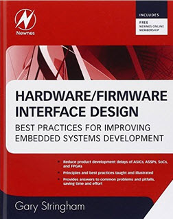
This month I'm giving away a copy of Gary Stringham's excellent Hardware/Firmware Interface Design.

The contest will close at the end of January, 2016. It's just a matter of filling out your email address. As always, that will be used only for the giveaway, and nothing else. Enter via this link.

Fancy IDEs?

Charles Manning had some thoughts about fancy IDEs:

I read with some interest the increase in people using online/web-based development tools etc. While these tools might be OK for some prototyping work and development of once-off products, they are not at all appropriate for most of the products I work on.

Many of the products I work on have 10-15 year support windows. That means all the development and manufacturing tools must be supported (or in some way supportable) for that long.

I've been bitten many times by equipment getting obsolete and finally dying or old versions of code no longer being available. Stuff that is online and is far less controllable is even worse.

Consider one of my clients....

They have a whole lot of software that uses a specific C compiler for an older CPU. The original engineer was one of those clever sods who thought it a good idea to use fancy compiler pragmas to get what he wanted. Unfortunately none of those pragmas are portable. So that code base is pretty much stuck with that compiler.

Worse still, the compiler is locked to a dongle. That dongle needs specific drivers that only work in a Windows XP computer.

Due to some timing issues, it won't work on modern PC hardware either.

Upgrading to a newer version of the compiler does not work because it does different things with the clever pragmas.

So basically we have a bunch of non-portable code that is stuck in a time warp on a computer that can't be upgraded. One day that computer will die and their luck will run out.

At least these people could make a backup plan of sorts by putting two old XP computers in storage, but the same basic problem exists for people using online tools, just that there is no way they can make a backup plan.

Give me IDEs for code editing and code navigation, but for the actual code and project set-up, I prefer real simple stuff: fully portable C (no decorations) with make files etc. The project should just build without fancy IDEs, XML or such.

Over the years I've heard from many engineers that their development environment wouldn't run on the latest version of Windows. So they stash an old Windows machine in storage in case maintenance is needed. But that's no guarantee; capacitors go bad with age so that old machine may not run.

Some companies are required to support a product for 30 years (notably in the railroad industry). 30 years ago the current version of Windows was 1.0. Linux didn't exist. The Mac was only two years old and used floppies, a 68000 processor, and a long-defunct OS. Just this week I heard from a developer who needed to get files off an 8" floppy disk drive!

In the 1980s I got a contract to change some code, which had been developed on a paper-tape-based system. There wasn't enough of a budget to port it to a newer environment, so I delivered the updated code on paper tape.

We may have a new problem looming - solid state disks. Archive a system for anticipated maintenance use a decade or more hence, and the SSD may drop bits since flash memory has a limited life. For example, Spansion's S34ML04G1 device has a ten year (typical; no minimum is rated) data retention period.

Long-term support in an age of constant technical revolution is an enormous problem.

Choosing EDA Tools

Andrew Retallack wrote:

I have to add my comments to Luca Matteini’s recommendation of Digikey’s PCBWeb.  I am generally cautious about using any distributor-sponsored tools, as I fear that they exist by the good grace of the marketing departments.  If I end up being one of only a few users, and the company decides the "experiment" is a costly failure, I could be left with a bunch of schematics in an unusable format once the tool is "retired."  To mitigate that risk I chose KiCad - a tool with an extremely active community of developers as well as support from CERN.  So I'm fully behind Margaret Johnson's comments.

A while back I wrote a post on how I chose my EDA tool and came up with these 5 considerations:

1. Free isn't Really Free
There are many tools available that are "free" - free to install that is. You need to remember that your time isn't free. It'll take time to get to know how the tool works, come up with a good workflow, learn how to design components and footprints… and more!

2. The Commercial Model
It's very rare to actually get software for free - unless it’s open-source (e.g., KiCad). It just doesn't make commercial sense. So developers rely on various models to earn their revenue. The "big boys" sell their software right-out, but at prices that usually puts them way out of reach of enthusiasts. Some work on a "freemium" model, where you pay to unlock additional features. Others are sponsored by distributors, and integrate into their systems so you can order parts (from them!) right out of the package (Digikey, Mouser and RS Components do this). Still more rely on you using their software through to manufacturing, where they make their money. You need to make sure you’re comfortable with the commercial model.

3. Platform (In)Dependence
This is a quick way to whittle down your options. Unless you're prepared to switch operating systems for a software package (or go down the road of creating virtual machines), then you’ll quickly be able to eliminate packages. Nowadays there are also a number of web-based solutions (e.g., Upverter), which remove this consideration - however you need to comfortable that you'll only be designing PCBs while you’re connected to the Internet.

4. Support and Community
If you're diving into a new software package you're going to want to ask people for help; or at the very least have access to a decent set of tutorials. In the past I've found some good tutorials for Eagle, and more recently an excellent set of tutorials for Kicad from Contextual Electronics. You'll also need an active community of users to ask for help.

5. Feature Set
Finally, this is possibly the most important consideration. Many packages have similar features, but of course the usability varies widely - unfortunately this is only something you’ll realise once you've started working in the tool. Taking a look at tutorials beforehand will help to give you an insight into how easy the tool is to use, but you'll really only know when the rubber hits the road and you're designing your own PCB. When I considered packages, the one feature I didn't consider was the auto-router - I don’t generally use the auto-router as I don't trust it to make the best layout decisions; and besides, I enjoy the puzzle of routing my own boards.

PCB Software

Paul Carpenter has some thoughts about PCB software:

> Luca Matteini had some thoughts about PCB layout software:
>
> In the last few years, some higher end tools have been sponsored by
> large distributors in a stripped down version, see RS (DesignSpark),
> Farnell (Cadsoft Eagle), Mouser (MultiSIM Blue), and Digikey (Designer
> Schematic and Layout).

There starts the problem if you are making 10 off or less as a ONE time build or for a magazine article this is great. Any real production these tools and putting the DISTRIBUTOR stock code (if you are lucky) in and hopefully for the right variant. By production I mean making in batches of 100 or more for longer than 6 months, and/or supporting for longer than 2 years.

I speak as someone who is trying out Kicad, long time user (and contributor) for Cadsoft Eagle, have used Orcad for a few years and even older packages going back years that used to run on VAXes.

Also a few years experience in running a purchasing department for small volume high value products in the late 80's, where the MONTHLY credit limit direct with one chip manufacturer then was £250,000 (over that time period $300,000 to $500,000), to the extent that we were ordering 5000 RAM chips a month and over 12,000 of one other device a month. Various manufacturers and distributors were continually fighting to get our Flash ADC business. This started when the only real choice was TRW at $500 a piece and each product had 4 in.

Most people and CAD packages WRONGLY use the Circuit Schematic to generate the BOM, where they should be using an assembly drawing. Some of the failings of schematics are:

1/ Inability to allow STACKED components that can be incorporated into a BOM
(even as distributor stock code)

a/ Components in sockets or holders
b/ Additional components like light pipes, holders, mounting screws, rack mounted boards needing handles and their components, cConnectors e.g., D type nut and bolt secure to board and additional, 4-40 spacer, washers and nuts
c/ Special processes like clips or soldered wires to hold down parts.
You may need to list these on BOM

2/ Having lots of strange symbols on the schematic for mounting holes and additional hardware.

3/ Programming for micros and PLD/FPGAs these should have a separate part number if programmed before board assembly which for off-shore or contract manufacturing is often done.

4/ Databases that are tied to assuming a single source for every component. These are difficult to edit or maintain, you need to start with at least one manufacturer part number as the definition.

5/ Worst still one part number is tied to a symbol so this becomes even worse for things like the humble resistor with loads of variants

a/ value (E12,E24,E36,E96 or even custom)
b/ tolerance
c/ through hole, SMD, screw terminal and others
d/ Wattage
e/ Temperature coefficient
f/ Temperature range
f/ body colour (affects some assemblies where a few values are used and body colour is used to distinguish value)
g/ Voltage rating (yes those resistors most of you use are rated at 100V only and I have used 500V and higher resistors).

6/ Acceptable substitutes for THIS DESIGN, as in other manufacturers and variants from same manufacturer, Examples:

a/ Can we use lower or higher tolerance or voltage rating etc..
b/ Speed grades you may use -10 variant now but later on manufacturer may discontinue that and produce only higher speed grades. Alternatively there may be glut of higher speed grade available now or cheaper.

7/ Is it possible to list TWO or more manufacturers EASILY, then import, export or merge the databases with purchasing's or production database

In all the packages I have used and looked at NONE of the above is easily done.

I export the schematic BOM to assembly drawings and spreadsheets with ALL the additional info added, then amalgamate information before purchasing or getting manufacturing.

Recently I provided to Cadsoft a new BOM ULP (User Language Programme, additional interpreted C-like language to add extra functions to Cadsoft Eagle ) that did simple things like improve code efficiency, sort BOM so you had one line for a value and all the board references together, then actually sort the output so all the C<x> components were together, then D<x> etc, then be able to print it without stupid line wraps in a readable manner for someone to use for manual assembly or referencing for pick and place setup.

> First, it lets you produce your Gerber files, and save files locally.
> Schematics and PCB files are in XML format, without complex data bases
> storing everything you did after your birth. Then it produces a nice
> BOM with parts directly from DigiKey, with an updated board cost and
> the options to export it for an order.

I tend to use PCB manufacturers who will accept my CAD board files especially on small runs, see above for BOM fallacy.

> They also sponsor a few PCB makers, from which you can have an
> automatic quotation on your PCB cost, and optionally order fabrication
> (unless you don't want to do something else, since you have Gerbers).
> The application is quite simple to use, and for a professional maybe
> exposes too few options to choose from, but the feeling is good.
>
> It's even quite good at moving some already routed components on PCB,
> without disrupting the tracks.

I would expect and PCB layout package to do that.

Often missing from PCB CAD packages:

1/ Lock outline, mounting holes, part placement or specific tracks or polygons due to other considerations. The times I have dealt with problems with other peoples layouts that have been up-rev'ed and a part has moved and not been put back correctly. Worst still inner planes moved and now a via only connects on half the via to a polygon.

2/ Change Thermal Relief per component so a soldered on heat sink actually has lots of copper connection

3/ Has Net class rules that realise that a 2mm power grid can thin down to 0.4 mm to connect to a pad

4/ Not auto thermal relief between adjacent SMD pads looking like a short between pins

5/ If laying out for laser or other optical layout (not UV or X-ray) stop converting and laying out parts to 0.0001 mm accuracy and getting lots of things not joining or having inability to connect to correct part.

6/ Track is only finished when connected to centre of pad/via to 0.0001 mm accuracy.

7/ Ability to have Panellising as a function of the package not add on script.

8/ Ability to use the Board outline and placement directly to create an assembly drawing and special notes like gold plated contacts area. Adding of handles, manually added components. This should be the start point for the BOM.

7/ Many other issues ranging from incorrect automatic vias inside a via, lack of documentation that fails to keep up with releases to worst of all BAD software practice that relies on Terrahertz CPU and Exabytes of RAM.

Example of last from a PCB CAD package script to produce a BOM as SUPPLIED with the package, note strings can be up to 4096 bytes long

 string  StripWhiteSpace (string s)
              {
              while (s && isspace (s[0]))
              s = strsub (s, 1);
              while (s && isspace (s[strlen (s) -  1]))
              s = strsub (s, 0, strlen (s) - 1);
              return s;
              }

Replaced in my contributed item with

string  StripWhiteSpace( string s )
              {
              if(  s )
              {
              int start, end;
              start = 0;
              end = 0;
              while( isspace( s[ start ] ) )
              start++;
              end = strlen( s ) - 1;    // get last index
              while( isspace( s[ end ] ) )
              end--;
              s = strsub( s, start, end - start + 1 );
              }
              return  s;
              }

Faster executing and much less of a memory hog.

> Libraries are on-line, and the mix of schematic parts, footprints and
> DigiKey codes works quite well, while new parts may need a few work,
> if you plan to keep in sync with DigiKey catalog.

Most supplied libraries I have dealt with are more artistic than practical especially for manual testing or assembly, even things like cathode on a diode is not on ident layer but a documentation layer. Don't even start me on the ones who want to draw every single leg of 100 pin and above device in a documentation layer over a pad, making ident layer more complex to produce and hiding pin 1 references from the board when testing.

Jobs!

Let me know if you’re hiring embedded engineers. No recruiters please, and I reserve the right to edit ads to fit the format and intents of this newsletter. Please keep it to 100 words. There is no charge for a job ad.

Joke For The Week

Note: These jokes are archived at www.ganssle.com/jokes.htm.

Q: "Whats the object-oriented way to become wealthy?"

A: Inheritance

Advertise With Us

Advertise in The Embedded Muse! Over 25,000 embedded developers get this twice-monthly publication. .

About The Embedded Muse

The Embedded Muse is Jack Ganssle's newsletter. Send complaints, comments, and contributions to me at jack@ganssle.com.

The Embedded Muse is supported by The Ganssle Group, whose mission is to help embedded folks get better products to market faster.