|
|
|||
You may redistribute this newsletter for noncommercial purposes. For commercial use contact jack@ganssle.com. To subscribe or unsubscribe go to https://www.ganssle.com/tem-subunsub.html or drop Jack an email. |
|||
| Contents | |||
| Editor's Notes | |||
How do you get projects done faster? Improve quality! Reduce bugs. This is the central observation of the quality movement that totally revolutionized manufacturing. The result is a win-win-win: faster schedules, lower costs and higher quality. Yet the firmware industry has largely missed this notion. Deming et al showed that you simply can’t bolt quality onto an extant system. But in firmware there’s too much focus on fixing bugs rather than getting it right from the outset. In fact it is possible to accurately schedule a project, meet the deadline, and drastically reduce bugs. Learn how at my one-day, fast-paced Better Firmware Faster class, presented at your facility. There's more info here. Jean Labrosse's books about his uC/OS-II and uC/OS-III real-time kernels are reputedly the most popular books ever written about embedded systems. Now they are free in PDF form on Micrium's web site. Also free are Christian Légaré's books about uC/TCP. These are great references about RTOSes and the protocols behind the Internet. |
|||
| Quotes and Thoughts | |||
"C is quirky, flawed, and an enormous success." - Dennis Ritchie |
|||
| Tools and Tips | |||
Please submit neat ideas or thoughts about tools, techniques and resources you love or hate. Caron Williams wrote: Even though it's now about 40 years old, 'The Mythical Man Month' [Fred Brooks] still has many very relevant and powerful things to say to electronics and software engineers. I'm sure you've read it, and I'm pretty sure you endorse my statement. However none of the newly graduated engineers I've interviewed in the past 20 years have heard of it! As you said: none, nada, zilch, etc. I would make it required reading for anyone about to embark on a software project, and the lessons it contains are applicable to hardware design too. Ken Smith has a different take on accessing hardware registers in C++. His paper about this is here and Ken's description is: Everything about a hardware register is listed in the datasheet for the processor or peripheral. We know its address, its offset with the word if any, and we know whether the register is readable, writeable or both. Therefore, we know how to refeine a register or any of its subfields at compile time. Many register manipulation techniques exploit some of these pieces of a priori knowledge to ensure safety and efficiency but none I have seen so far exploit them all. This article presents an approach for hardware register access in C++ that puts all of this a priori knowledge to use to help ensure safety without sacrificing efficiency. Ken goes on to say that Martin Moene had a similar idea, published here. Ken welcomes feedback to kgsmith@gmail.com. |
|||
| What I'm Reading | |||
http://arxiv.org/pdf/1209.3099 - A cache management strategy to replace wear leveling techniques for embedded flash memory. |
|||
| Datasheet Rant | |||
It's all about the code - unfortunately. As mentioned above it's hard to get concrete information about the Kinetis' L series power consumption. But that's a common problem today - datasheets increasingly lack the electrical information a design engineer needs to both select a part and properly design it in. One ARM part I've been playing with has a 1100 page user's manual. There's plenty of information about programming the various registers to use the low power modes - but not a peep about exactly how many micro- or milliamps will be consumed. What about clock rate? Sure, that's specified and, with enough patience a superhuman engineer will master the enormous number of modes and registers needed to control the various clocks. But what does clock rate even mean? Execute out of the on-board flash and will wait states be injected? The datasheet gives no hint. I ran some experiments and found that with the part screaming at it's rated 200 MHz the thing fetches 55 million instructions/second from internal flash. Now, as an old-timer who was once content with 2 MHz devices that needed several T-states to handle each instruction, that 55 million is a very impressive number. But it's a lot less than one might be led to believe going on the raw clock rate. (Execute out of external memory and no matter how fast the thing can swallow clocks it may be slowed to a crawl. One eval board here runs at hundreds of MHz but the external flash is 70 nsec, and the RAM not much better at 55 nsec. That makes the cache-less single-cycle CPU loaf along at an effective rate of less than 20 MHz. There are some very interesting technologies used to improve this in some cases - ST's adaptive real-time accelerator being an example. But estimating performance has become very complex. Clock rate alone means little.) Datasheets are getting huge as the number of peripherals grows. But it has been a long time since they were mailed on paper (another part I know needs almost 5000 pages - print that and you'll use an entire box of paper). PDFs make production costs zero. Vendors do us a grave disservice when hand waving and marketing "product briefs" substitute for cold, hard numbers. |
|||
| Watchdogs Woven Wright | |||
| Ode to the Teletype | |||
Long before computers existed, before transistors - let alone ICs - were a gleam in anyone's eye, machines transferred serial data between themselves. The serial protocols we now implement with thousands of gates are hardly new; indeed, it's amazing to remember that our highly integrated communications devices are sometimes just modern versions of purely mechanical machines. The invention of the typewriter changed the face of business as clerks no longer needed the precise handwriting skills of before. Inventors quickly realized that the typewriter also simplified the creation of printed words; the measly few dozen characters on the keyboard let operators construct any word, and indeed any book. Samuel Clemens, AKA Mark Twain, had one of the first typewriters, which is still on display at his house in Hartford Connecticut. (Which is a really interesting stop if you're in the neighborhood). Smart folks tried a variety of schemes to build automatic typewriters which could send data over a phone line to another such device. Eventually the Teletype company, later acquired by AT&T, came to dominate the industry. In Teletype's parlance these machines are properly called "teletypewriters," but common usage used the company's name for the machine. Much like we've turned the proper noun Xerox into a verb meaning "to copy." Teletypes used mechanical linkages exclusively to encode and decode characters into bit strings. There were no active elements in these units. Even before World War II teletypes clattered noisily in the back of newsrooms and other facilities. Often these units had no keyboard, being nothing more than the old-time equivalent of a printer, spilling miles of yellow paper on the floor with the latest UPI wire reports. "Weather machines" were almost ubiquitous, as the fledging airline industry looked for ways to anticipate fogged-in airports. These special purpose teletypes had their own unique character set that concisely represented different atmospheric conditions. Tens of thousands of weather machines were installed, later creating a glut of these beasts on the surplus market. I acquired one in the early 70s, a model 15 Weather Teletype, for use on a 12 bit home-brew computer. It drove the neighbors crazy when noisily dumping listings at 3AM. But that's another story.
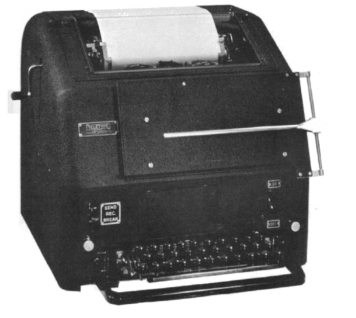
Model 15 TTY These early I/O devices managed, without the use of a single transistor or vacuum tube, to convert parallel data to serial, transmit it over a wire, and reconstruct that data stream onto paper. They were monuments to mechanical engineering. Those were simpler times, long before UNICODE or even ASCII. The machines spoke a five bit code call BAUDOT. Twenty six letters, 10 digits and miscellaneous punctuation marks needed more than the 32 characters possible in 5 bits, so two special codes selected what was in effect an alternate character set. The shift key as we know it today did not exist; instead, "Shift Up" and "Shift Down" keys transmitted their own unique characters, and caused the unit to move the platen to select the characters on the upper row of the hammers. Needless to say, all letters were capitals, a bit of history that doesn't quite seem to go away as even today on the Internet too many folks seem case-challenged, sending email consisting of all upper case or all lowercase letters. Maybe, like the Japanese soldiers who held out for a decade after the end of the War, these people are in technological hideouts, still using the tools of so long ago. A common accessory was the paper tape reader and punch, the only sort of long term data storage then possible. Operators could type their messages off-line, the punch recording each character as 5 data holes across a thin paper tape. Connecting the machine to the "net" they would then run the tape through the reader. Small metal fingers probed the holes, checking all 5 in parallel at once. To convert this parallel data stream to serial, the 5 fingers actuated switches connected to a device that strongly resembled the distributor in a car. Each switch went to a metal strip around the rim of the distributor; a spinning rotor dragged over each strip in turn, generating a stream of ones and zeroes, in serial, representing the character. It was breathtaking to watch. Incoming data was assembled in reverse, using the distributor to feed the serial stream to the metal strips as the rotor spun.
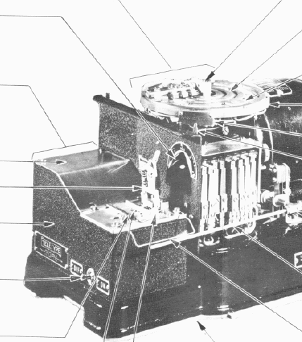
Distributor assembly
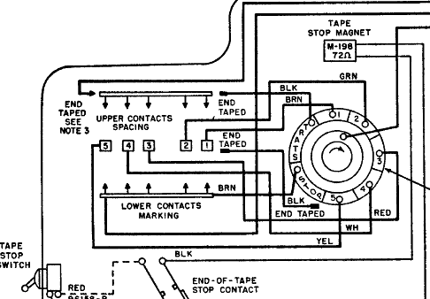
Distributor schematic: Note the five sense switches that "felt" for the holes in the tape and routed the 5 bit wide parallel signal to the rotary distributor's 5 contacts arranged around a central post. A wiper rotated around on these contacts and converted the parallel to serial (the center pin is the serial output). Clearly, though, the machines needed to transmit a tad more than just the five data bits. Something had to start the rotor spinning, in effect signaling the receiving machine that "hey, a character is starting to come." The sending machine therefore preceded each character with a "start" bit, a signal that fired up the motor at the other end. An awful lot of levers and linkages moved to print a single letter; the machine took a little bit of time to stop, and to put everything back to an idle state before the next character came. An idle time, therefore, followed every character. This time was never really part of the transmitted data, as it was just an interval when nothing was on the line. It became known as the stop bit, or bits when more than one was required due to slowly moving levers. RS-232 didn't exist then. Instead, these machines communicated via "current loop," a two wire interface where an open (like opening a switch) designated a logic one - the one signaling a start bit, for example - and a closed line meant a zero. When about 20 ma of current flowed through the circuit the system was idle. RS-232, by contrast, is a standard based on voltage, not current. Ones and zeroes are indicated by a few volts of negative or positive level. RS-232 also designates a number of additional wires used for handshaking and status indications. Current loop never needed handshakes - if the teletype wasn't ready it just missed the data. Tough. At the dawn of the microprocessor age the ASR-33 Teletype was still the standard way to communicate with computers. Video units were simply too expensive for most small systems. By the 70s ASCII was firmly entrenched and had replaced BAUDOT as the lingo of the teletype. Still all upper case, at least the Shift-Up/Down characters had been relegated to the dusty bin of abandoned technologies.
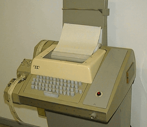
Model 33 TTY Operating at a blinding 10 characters per second, this mechanical beast was no doubt the cause of many ulcers and crimes of frustration. The teletype needed 8 seconds to print one line of output. Think about it - 8 seconds per line. The 10 character/second rate became a de facto standard. 110 baud came from the one start, 8 data, and 2 stop bits transmitted 10 times a second by these machines - 110 bit periods each second. Desperate for better speeds someone found that the ASR-33 generally behaved well with only 1.5 bit periods for the stop bit. As UARTs got smarter quite a few supported 1, 1.5, and 2 stop bit generation. Today we live in an age of no moving parts. It's hard to imagine the complexity of one of these machines. A bewildering array of levers moved faster than the eye could see. Yet the machines were amazingly reliable. When problems did occur a few taps in the right place with a hammer usually got the machine going again. I wonder if there's a landfill piled deep with this detritus of progress, the old teletypes, 545 scopes and 300 baud modems. The ASR-33 included a paper tape punch and reader. Even into the early 70s tape was a standard storage media. All microprocessor programs, both binary and source, were stored on paper tape. Even in the minicomputer age DEC and Data General distributed most of their code on fan-fold tape. You sent in your money for a Fortran compiler and received a two inch stack of tape. This was long before code bloat changed the computer world. The micro world followed many of the models of minis at first. The first microcomputer systems looked a lot like a mini, with the same front panel switches and LEDs, and of course the teletype interface. It's interesting to see how technologies converge at critical moments in history. The microprocessor would have flopped without DRAMs, invented just a few years before. The UART similarly came along just at the right time. Intel's 1972 Intellec 8008 development system used a General Instruments UART to talk to the teletype. Had the UART never been invented then probably we'd use "bit banging" software to do the serial to parallel (and reverse) conversions. Though not difficult, this requires a deep understanding of the timing of each instruction used to ensure the code reads the serial input stream at exactly the right point in a bit field. Despite the availability of cheap UARTs, even today some firmware does indeed use bit banging. As a college kid I was tapped to work on an 8008 project. This embedded instrument was coded in assembly language. Our development environment consisted of an Intellec microcomputer from Intel (an 8008 machine with - fully loaded - a breathtaking 16k of RAM), an ASR-33 Teletype, and software tools. Intel did quite a good job supplying the nascent micro community with software tools. We'd start work with their rudimentary editor, supplied on paper tape, entering and modifying the assembly source code. With no disk storage we'd finish editing and punch out a tape of the program's source. Then we'd load the assembler - also on tape, also loaded over the ASR-33's painfully slow 10 cps reader. Today tools work so transparently that we forget assemblers and compilers read the source file at least two or three times, to resolve forward references and handle macro expansions. Intel's old 8008 assembler was a three pass product, so we loaded the assembly source file - uh, tape - three times. On the third pass it punched out a binary image of the assembled module. An aftermarket of very clever but ultimately restricted one-pass assemblers all offered much faster assembly speeds. These products, too, are now in the landfill of abandoned technology. After assembling all of the modules, with a binary tape for each module, we'd load the two-pass linker, itself yet another inch high stack of tape, and then run all of the binary tapes through twice. The result was a single absolute image, on tape, we'd load into the debugger. Needless to day, the ASR-33's speed made this an awfully tedious and slow process. A 4k program took 3 days to assemble and link. As young sorts with too much ego and not enough software design experience, our bug rates were high enough to make any thought of reassembling after finding each bug absurd. Like most developers of the time, we'd patch the code in the debugger. This meant entering in new hex codes to fix incorrect instructions. To add more code we'd patch in a jump to an unused area of RAM, hand assemble mnemonics, and jump back. As we patched and patched, the code diverged from the master source tapes. We'd punch binary images each night to make a record of the changes, but the ASR-33 was so slow that reassembling from clean source files was a luxury rarely indulged. With time fast paper tape readers became available to the micro world. That 10 cps ASR-33 speed shot up to 300 characters per second on a high speed optical reader, greatly reducing development time. Spending a small amount of money on capital equipment yielded vast improvements in efficiency, a lesson still not learned today. Tape gave way to cassettes, and finally floppies became the technology de jour. High level languages have made patching object code a thing of the past, except in extreme circumstances. Embedded tools are still far from perfect, but have shrunk the edit/compile/download cycle to something much closer to the ideal (zero time) than ever before. Yet the legacy of the Teletype still exists. Every RS-232 connection uses a data stream no different, except in levels, than that pioneered by the teletype. UARTs, electronic equivalents of the old pseudo-distributor, are a standard feature on embedded processors. You could connect an ASR-33 to your PC or embedded system even now, using nothing more than a couple of transistors to shift the RS-232 voltage levels to current loop. Many UARTs, including the 16550 used in PCs, still support 1.5 stop bits, a bit of old teletype history we're still carrying along. The more things change, the more they stay the same. |
|||
| Jobs! | |||
Let me know if you’re hiring embedded engineers. No recruiters please, and I reserve the right to edit ads to fit the format and intents of this newsletter. Please keep it to 100 words.
|
|||
| Joke For the Week | |||
Note: These jokes are archived at www.ganssle.com/jokes.htm. From Mike Bellino: Q: How do the Eskimos log onto Facebook? A: They use the WINTERnet! |
|||
| About The Embedded Muse | |||
The Embedded Muse is Jack Ganssle's newsletter. Send complaints, comments, and contributions to me at jack@ganssle.com. The Embedded Muse is supported by The Ganssle Group, whose mission is to help embedded folks get better products to market faster. |


