A "Nano-power System Timer" looks great but misses the mark.
I recently came across TI's TPL5110 chip which bills itself as a "Nano-power System Timer for Power Gating" device. At first glance it's an intriguing part for ultra-low power systems.
It has a number of modes, but is basically a timer whose interval can be set via an external resistor.
It's for systems that have to wake up periodically to do something, like log data from a sensor, and then go idle. The TPL5110 uses a resistor to set the time interval, and gates power to the microcontroller via an external FET. Such a system might look like this (from the datasheet):
Typical TPL5110 system.
When the processor is finished doing its business it asserts a "DONE" GPIO to the TPL5110 which turns the FET off. The MCU is powered for exactly as long as needed to get the required work done.
With the MCU turned off, and the TPL5110's worst-case current needs of a tiny 50 nA, battery life will be very long.
Cool, huh? But on reflection I don't see a practical use for the device.
A FET in the off state still leaks some current. How much? I have never seen parametric tables where source-drain leakage was a data item one could use in selecting a FET, so we have to plow through lots of datasheets to get a sense. It seems P channel MOSFETs run maybe as low as 100 nA to 10 uA or so – at 25C. This gets wildly worse as the temperature increases, generally by a couple of orders of magnitude.
This means with the FET off the current leaked to the microcontroller is more than the sleep current most modern MCUs need (anywhere from tens of nA to a uA or so). Why not just go into a sleep mode and save some money and PCB real estate?
To use the TPL5110 one would have to be very careful in selecting the FET. At the low currents needed to drive the FET's gate the device's output voltage can be as high as 0.3V. A LiMnO2 coin cell is dead at an unloaded 2V. If everything were perfect, the best one could hope for would be a VGS of -1.7V when the battery approaches end of life. A lot of FETs exhibit a high RDS(on) with that level of bias, so the MCU might not get enough voltage to operate.
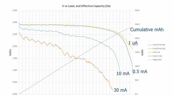
Actually, a battery at 2.0 volts might not be dead. As I showed in some research on designing ultra-low power systems, coin cells have an internal resistance that increases as they are drawn down. Unloaded you could see almost 2.5 or more volts; drop on 10 mA and the voltage at the battery's terminal, that which goes to the FET's source, may be under 2.0.

Battery voltage as a function of load and state of charge.
I'm a huge fan of TI's components, and have been using them for the better part of half a century. But the TPL5110 seems an IC without a mission. Perhaps one application is with old-fashioned MCUs that suck lots of juice when sleeping, but if it were me I'd just use a more modern controller. TI has a lot of great devices that would fit the bill. An example is the MSP430F15x, which has a sleep mode with a max current draw of 0.5 uA at 25C.
Thanks to Mike Lease of Cmicrotek for his thoughts about this.
Published July, 2016

